5. Conclusions
5.1 Simplified optical link model for transmission of a carrier
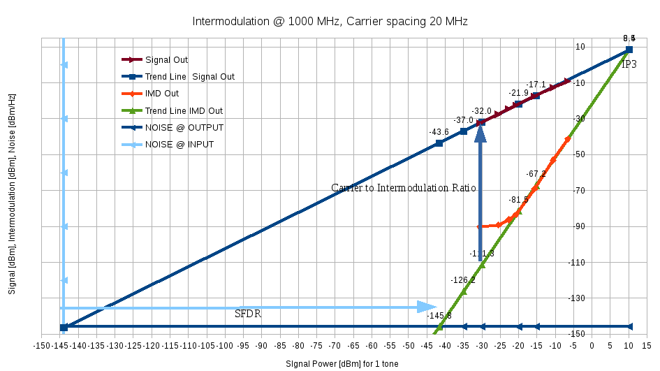
The model is based on the Spurious Free Dynamic Range graph :

Figure 2. RF frequency respone (for several RF input powers).
- RF output power and related gain ;
- Output noise ;
- 3rd order intermodulation products.
It is possible to calculate Carrier to Noise, Carrier to Intermodulation and Carrier to Noise & Intermodulation ratio.
5.2 Link comparison : Optical link vs Coaxial Cable for 30 m link length (like in a home)
In the following table, there is a comparison between coaxial cable to optical link.
| Parameter | Coaxial Cable | Optical Link |
|---|---|---|
| RF Gain @ 950 MHz [dB] | -3.6 | +0.5 |
| RF Gain @ 2150 MHz [dB] | -5.6 | +3.0 |
| Noise Figure @ 950 MHz [dB] | +3.6 | +30 |
| Noise Figure @ 2150 MHz | +5.6 | +33 |
| IIP3 [dBm] | +50 | +10 |
| SFDR [dB/Hz2/3] | +145 | +102 |
| LNB remote supply | Yes, supplied through coaxial cable | No, supply close to antenna for OTX required |
| Current Consumption [mA] | 0 | 700 mA / 12 V |
| LNB telecommand | Yes | No |
| Bidirectional link | Yes | Yes, but with additional hardware |
| Cost | Low | High |
For a distance of 30 m, optical link is not justified : performances and cost are not competitive with coaxial cable.
