Intermodulation » History » Version 18
« Previous -
Version 18/24
(diff) -
Next » -
Current version
HAENNIG, Gerald, 12/14/2015 01:36 PM
- Table of contents
- 3.3 Intermodulation (IMD)
3.3 Intermodulation (IMD)
3rd order Intermodulation measures the major contributions to the non-linear distortions on the signal.
3.3.1 Creation of two tones for Intermodulation test
To measure the intermodulation in our system is necessary to generate two sinus at the input of the optical system and to evaluate them at the output. As the signal generator couldn't provide two sinus at the same time it has been decided to use the USRP with a Labview program to do so.
An already programmed Labview example in which one tone was generated was modified in order to do so:
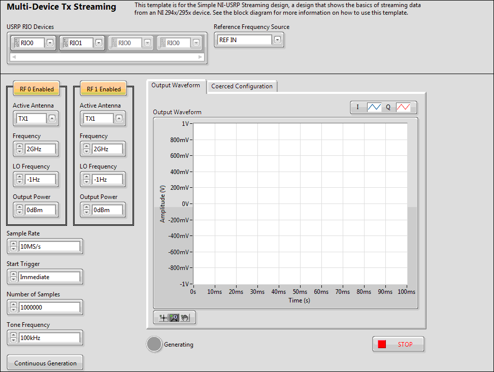
Figure 1. Front Panel used to generate two sinus
Then, the part of the Labview block in which the tone was generated was duplicated, adding a new output and having the result observed below:
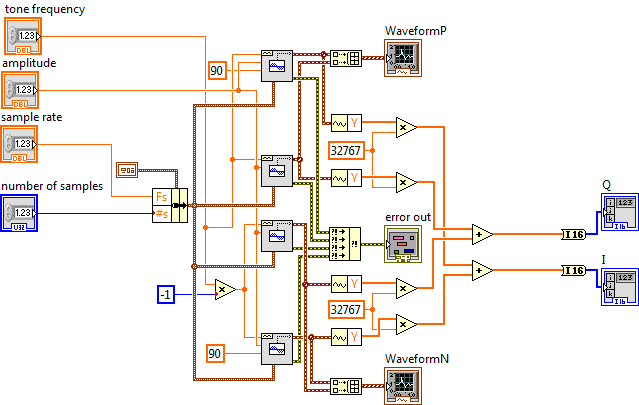
Figure 2. Block modified to generate two sinus
After the Labview modifications it could be observed at the output of the USRP the two tones:
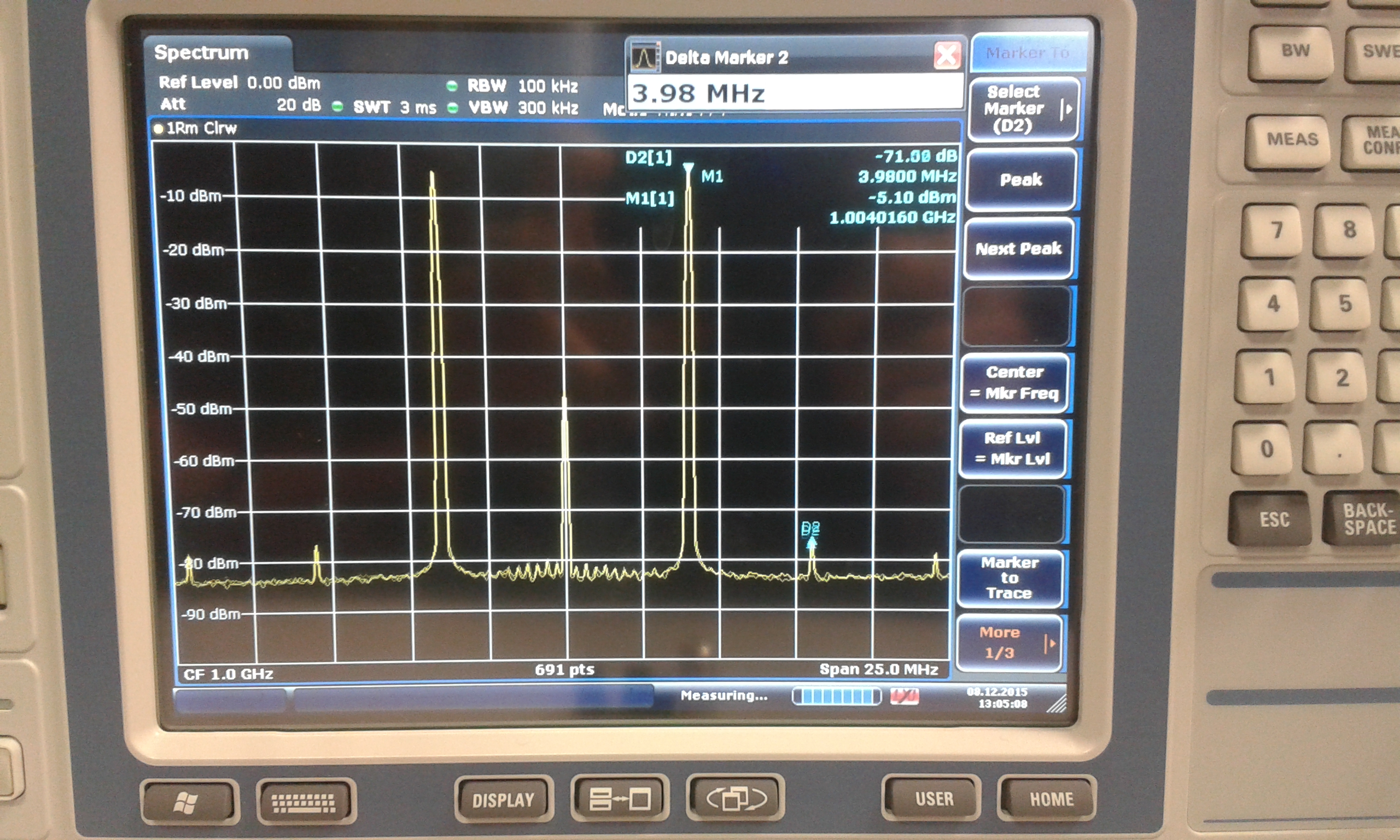
Figure 3. Two sinus output from the USRP
3.3.2 Measurement results
In Figure 4, 5 and 6 we can observe the different intermodulation results for 0.7, 1 and 2 GHz:
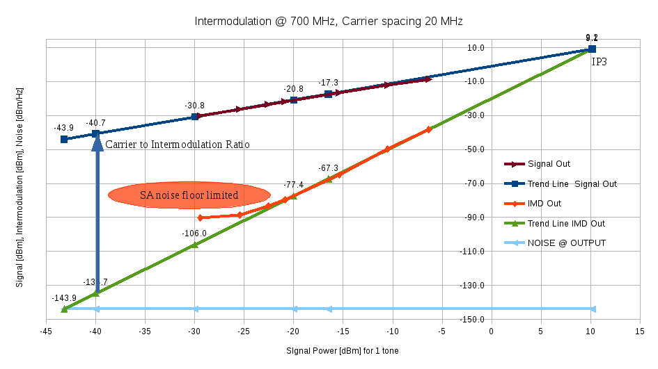
Figure 4. 3rd order Intermodulation vs Input Power @ 700 MHz
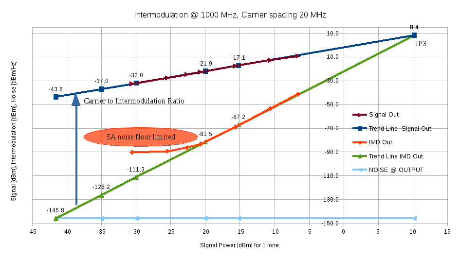
Figure 4. 3rd order Intermodulation vs Input Power @ 1000 MHz
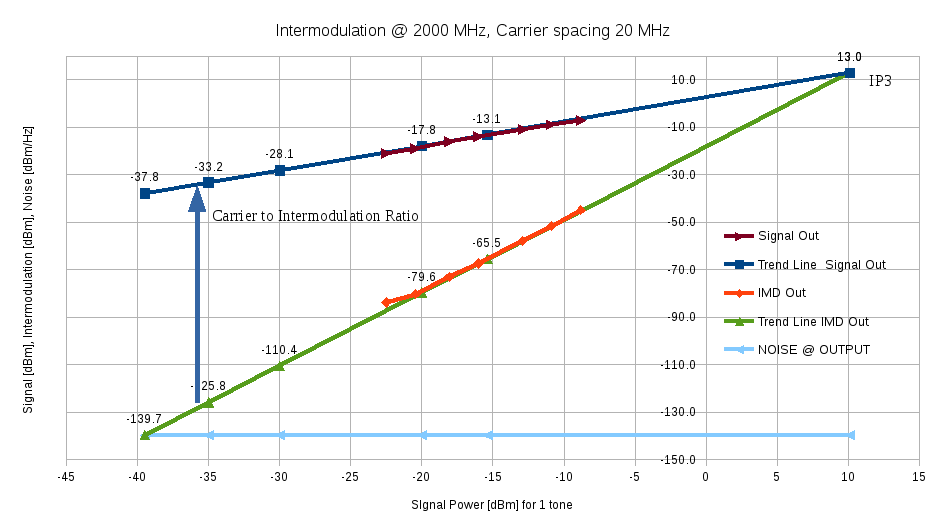
Figure 6. 3rd order Intermodulation vs Input Power @ 2000 MHz
- 1:1 slope for the signal (f1 or f2) : IMD is more important as the output signal increases;
- 3:1 slope for 3rd intermodulation product (2*f1-f2 or 2*f2-f1);
- IP3 point, intersection between linear & intermodulation lines : 3rd Order Input Intercept Point is the metric to characterize such a non-linearity.
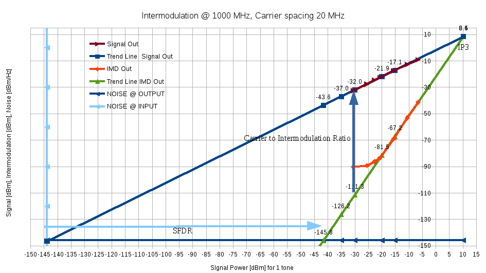
Figure 6. Spurious Free Dynamic Range (SFDR) @ 2000 MHz
